1 2 3 4 5 6 7 8 9 10 11 12 13
For this example we will start with windows and use the Borland C++ Builder as programming language. The advantage of this combination is, that windows is for historical reasons probably the most familiar operating system to many readers and Borland Builder has the advantage, that with Kylix, there is a very similar programming environment under Linux. If you don't have included the gl.h library n the path of your compiler, you should add the corresponding #include. By the way, you shouldn't use the gl.h library that shipped with your compiler and is typically in the default path of the compiler, because this is usually pretty old. For drawing the scene you need some sort of update loop. You can solve this problem by either using a thread or the OnIdle function. For our applications I prefer the OnIdle function because threads have some overhead (if you think about programming a game things might become different ;-) In the TFormMain procedure we define our update loop function (I call it IdleLoop) as idle function.
//---------------------------------------------------------------------------
TFormMain::TFormMain(TComponent* Owner)
    : TForm(Owner)
{
    Application->OnIdle = IdleLoop;   	// Define idle function
}
In our IdleLoop we first request more time from the system (done=false), so that we have enough time to do all the rendering. Then we render the scene and after finishing we put the rendered scene on the screen (SwapBuffers). The reason for drawing into a buffer and then putting the finished picture on the screen is that the user shouldn't see the entire drawing process but only the finished results.
//---------------------------------------------------------------------------
void TFormMain::IdleLoop(TObject*, bool& done)
{
    done = false;               	// request more idle time from the system
    RenderGLScene();
    SwapBuffers(hdc);
}
In the FormCreate procedure we have to set up the actual OpenGL window. First we need a rendering context, so that OpenGL knows where it can draw. The rendering context can be obtained from the device context by using the wglCreateContext function. Finally we enable face culling and depth test and set the background color to black. The first three values of glClearColor should be between 0.0 and 1.0 and determine the color, that is used to clear the screen, the fourth value represents the alpha channel and should be 1.0 (which means no transparency at all). GlClear does the actual clearing and also initializes the depth buffer.
//---------------------------------------------------------------------------
void TFormMain::FormCreate(TObject *Sender)
{
    hdc = GetDC(Handle);           	// get device context from main window
    SetPixelFormatDescriptor();	    // initialize pixel format
    hrc = wglCreateContext(hdc);   	// use device context to create
                                   	// a rendering context
    if(hrc == NULL)
      ShowMessage("Creating Rendering Context failed.");
    wglMakeCurrent(hdc,hrc);       	// tell windows to use hdc and rdc
    if(wglMakeCurrent(hdc, hrc) == false)	// show message if MakeCurrent fails
      ShowMessage("MakeCurrent of rendering context failed.");
    w = ClientWidth;               	// width of main windows client area
    h = ClientHeight;              	// height of main windows client area

    glEnable(GL_DEPTH_TEST);	       // use depth buffering
    glCullFace(GL_BACK);	           // select backside of polygons for culling
    glEnable(GL_CULL_FACE);	        // cull backside of polygons

    glClearColor(0.0f, 0.0f, 0.0f, 1.0f);  	// clear background to black
    glClearDepth(100.0);            // set depth buffer to the most distant value
    glClear(GL_COLOR_BUFFER_BIT | GL_DEPTH_BUFFER_BIT);
}
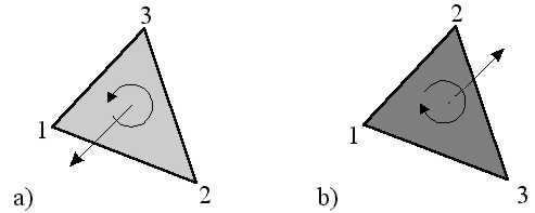
To understand backface culling and the depth buffer a little bit better, we have to take a look at how polygons are defined. In the most primitive case, the polygon is a simple triangle which is determined by it's three points:
glBegin(GL_TRIANGLES);     	// draw triangle
   glVertex2f( 0.0f, 0.0f);	// 1. point of the triangle
   glVertex2f( 1.0f, 0.0f);	// 2. point of the triangle
   glVertex2f( 1.0f, 1.0f);	// 3. point of the triangle
glEnd();
However there is some ambiguity, since we could list the points in clockwise or counterclockwise order. On the other hand, if you list the point counterclockwise and then rotate the triangle by 180°, it looks as if they were listed clockwise. Therefore the order in which you list the points can be used to determine whether we see the front side (counterclockwise listed points) or backside (clockwise listed points) of the triangle.
In many cases polygons form complex objects, where only the front side of the individual polygons (= object surface) can be seen. In these cases it is not necessary to take care of the backside, and therefore we can speed up the drawing by telling OpenGL to ignore the backside of the Polygon. This is done by the glCullFace(GL_BACK) command and then activated by the glEnable(GL_CULL_FACE) command. Although usually it doesn't make much sense, you could also ignore the front side of the polygons by using glCullFace(GL_FRONT). The idea behind enabling the depth test is almost the same: we tell OpenGL not to draw polygons, which are behind an other polygon and therefore can't be seen. To do so, OpenGL uses the so called depth buffer, which works very similar to the color buffer, but while the color buffer has stored for each pixel you see on the screen the appropriate color, the depth buffer stores for each pixel the distance of the object you see on the screen. When OpenGL has to draw a new object, it checks where it should be drawn, whether there is already an object drawn and if yes, the new object is only drawn, if it is nearer. In the later case, the distance of the new object is stored in the depth buffer.
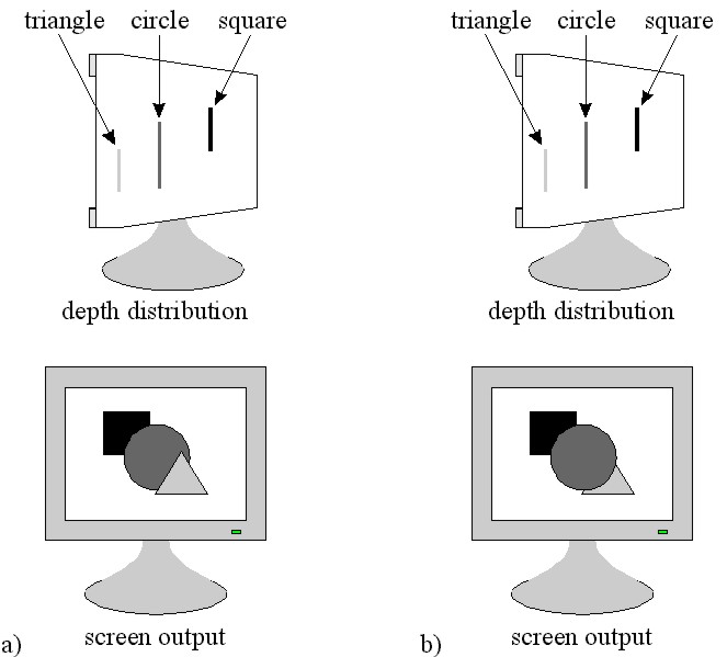
To get a better understanding, let's have a look at the example shown in Fig. 2. When we draw first a rectangle, then a triangle and finally a circle on the screen, where the square is farest away and the triangle is the nearest shape, we would expect, that the final image should look like Fig. 2a) - the shape in front covers the shapes behind. This is indeed the case, if we have enabled the depth testing. However in case that we have disabled it, the result might be a bit surprising: the circle is covering a part of the triangle. Although this result might be a bit unexpected on the first glance, it is actually straight forward: disabling the depth testing means, that all depth information (i.e. the z-coordinate) is ignored and therefore the shapes are drawn one on top of the other and therefore the last shape seems to be the "nearest", while the first shape seems to be the "farest". In the function SetPixelFormatDescriptor we tell OpenGL how we want to draw things.
//---------------------------------------------------------------------------
void TFormMain::SetPixelFormatDescriptor()
{
    PIXELFORMATDESCRIPTOR pfd = {
    	sizeof(PIXELFORMATDESCRIPTOR),          // size of the structure
        1,                                   // structure version
        PFD_DRAW_TO_WINDOW |                 // draw directly to window
                                             // (not to a bitmap file)
        PFD_SUPPORT_OPENGL |                 // allow DC to support opengl calls
        PFD_DOUBLEBUFFER,                    // use double buffer
        PFD_TYPE_RGBA,                       // use RGBA color mode (A = alpha)
        24,                                  // use 24 bit color
        0,0,0,0,0,0,0,0,0,0,0,0,0,           // not (yet) used
        32,                                  // use 32 bit z buffer
        0,0,                                 // not (yet) used
        PFD_MAIN_PLANE,                      // draw to main plane
        0,0,0,                               // not (yet) used
    };
    PixelFormat = ChoosePixelFormat(hdc, &pfd);  // choose and set the
    SetPixelFormat(hdc, PixelFormat, &pfd);      // appropriate pixelformat
}
Now that we have specified the pixelformat we want to use, we can take a look on how we could do the actual output. Basically we have 2 options: orthogonal or perspective view.

Orthographic Projection is needed for CAD-applications, diagrams and similar problems, while perspective projection is more suitable for displaying landscapes and bigger areas, where the effect is more obvious. Since for many of our applications the orthographic projection is more suitable, we will first take a look on how we can define the viewport in this case. The viewport maps the drawing coordinates to window coordinates and therefore defines the region of the scene, that can be seen.
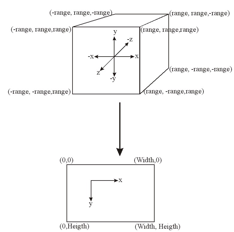
The OpenGL command used for defining the orthographic projection is
void glOrtho(GLdouble xmin, GLdouble xmax, GLdouble ymin, GLdouble ymax, GLdouble zmin, GLdouble zmax)
where we define the minimal and maximal value on each of the three scene coordinate axes. The Area of the Screen-Coordinates is defined via the Viewport:
void glViewport(GLdouble xmin, GLdouble ymin, GLdouble xmax, GLdouble ymax)
If you want to use a perspective projection, you have to use instead of the glOrtho the following command:
void gluPerspective(GLdouble fov, GLdouble aspect, GLdouble near, GLdouble far)
The parameters of this command need some additional explanation: the fov gives the field-of-view angle in vertical direction, aspect is the ratio of height to width and last but not least near and far give us the distances to the near and far clipping plane.

If the user resizes the window, we have to adjust the viewport and correct the aspect ratio. It is important to take care that h is not equal 0 because otherwise we get some problems when we calculate the new aspect ratio (division by zero). In the variable Range we define the range on the coordinate axes. This parameter can also be used to zoom in and out (zoom in by making Range smaller and zoom out by making Range bigger).
//---------------------------------------------------------------------------
void TFormMain::FormResize(TObject *Sender)
{

    GLfloat nRange = 100.0;

    w = ClientWidth;      // check new client width of the main window
    h = ClientHeight;     // check new client height of the main window

    if(h == 0)            // prevent a division by zero, by making sure that
    	h = 1;               // windows height is at least 1

    glViewport(0, 0, w, h);         // reset viewport
    glMatrixMode(GL_PROJECTION);    // add perspective to scene
    glLoadIdentity();               // restore matrix to original state

    if (w <= h)
        glOrtho (-nRange, nRange, -nRange*h/w, nRange*h/w, -nRange, nRange);
    else
	glOrtho (-nRange*w/h, nRange*w/h, -nRange, nRange, -nRange, nRange);


    glMatrixMode(GL_MODELVIEW);
}
After finishing all this preparatory work, we can finally take a look on how we can draw. The entire drawing is done in the RenderGLScene procedure, which con sists only of three commands: first we clear the color and depth buffer with the glClear command, then we call the actuall drawing procedure DrawObjects() and finally we tell OpenGL with the glFlush() command to put everything (all the graphic commands we used so far) on the screen.
//---------------------------------------------------------------------------
void TFormMain::RenderGLScene()
{
    glClear(GL_COLOR_BUFFER_BIT | GL_DEPTH_BUFFER_BIT);
    DrawObjects();
    glFlush();
}
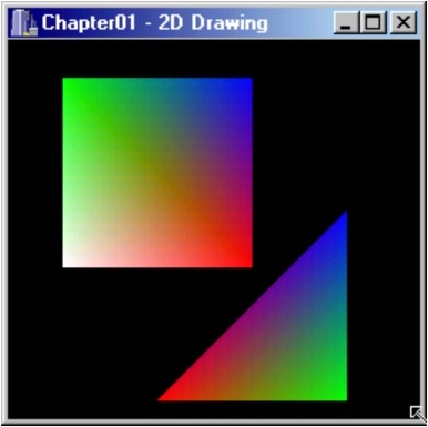
In the DrawObjects function we now can put our actual drawing commands. As an example we will draw a rectangle and a triangle. However instead of using the glQuads command, which usually would be used for a rectangle, we will use the glTriangle_Strip. The reason is, that for most practical purposes it is much easier to use triangles instead of quads since three points always lie in the same plane, while with four points this is - in general - pretty unlikely and may cause a lot of problems. As an additional bonus the hardware architecture of many graphic adapters is optimized to draw triangle based structures much faster than quads.
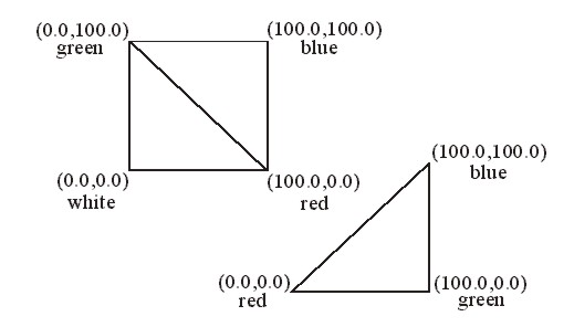
To draw the objects shown in the figure above we will use the following code:
//---------------------------------------------------------------------------
void TFormMain::DrawObjects()
{
   // rendering functions


   glLoadIdentity();                     // initialize drawing coordinates
   glTranslatef(-80.0,-20.0,0.0);        // move 1.quad to upper left sector
   glBegin(GL_TRIANGLE_STRIP);           // draw quad from 2 triangles
      glColor3f(1.0,1.0,1.0);            // set vertex color to white
      glVertex2f( 0.0, 0.0);
      glColor3f(1.0,0.0,0.0);            // set vertex color to red
      glVertex2f(100.0, 0.0);
      glColor3f(0.0,1.0,0.0);            // set vertex color to green
      glVertex2f( 0.0,100.0);
      glColor3f(0.0,0.0,1.0);            // set vertex color to blue
      glVertex2f(100.0,100.0);
   glEnd();                              // end of triangle strip
   glTranslatef(50.0,-70.0,0.0);         // move to lower left sector
   glBegin(GL_TRIANGLES);
      glColor3f(1.0,0.0,0.0);            // set vertex color to red
      glVertex2f(  0.0,  0.0);
      glColor3f(0.0,1.0,0.0);            // set vertex color to green
      glVertex2f(100.0,  0.0);
      glColor3f(0.0,0.0,1.0);            // set vertex color to blue
      glVertex2f(100.0,100.0);
   glEnd();                              // end of triangle

}
First we initialize the transformation matrix by loading the identity matrix with glLoadIdentity. This is needed to make sure, that we start at the coordinate origin. The glTranslatef command is actually not needed, we could simply change the coordinates used in the Vertex commands, but sometimes it is pretty useful to simply move an entire structure. With the first glTranslatef command we move the triangle 80 units to the left and 20 units down (remember the range is -100.0 to +100.0). With the glBegin(GL_TRIANGLE_STRIP) we tell OpenGL that the next vertices should be used to create a triangle strip (which is also very handy to draw all kinds of surfaces). The glColor3f command sets the color of the vertices (the parameters are the red, green and blue component of the color with a range from 0.0 to 1.0). The next glTranslatef command moves the drawing cursor 50 units to the right and 70 units down from the last drawing position - not from the coordinate origin! If the movement should be relative to the coordinate origin, we would have to call the glLoadIdentity() command before. If the Form has to be repainted, we have to redraw your objects and therefore we use the same commands as in the glRenderScene() (of course we could also call the glRenderScene() directly).
//---------------------------------------------------------------------------
void TFormMain::FormPaint(TObject *Sender)
{
    glClear(GL_COLOR_BUFFER_BIT | GL_DEPTH_BUFFER_BIT);
    DrawObjects();
    glFlush();
}
Finally before the program closes, we have to free the memory and delete the rendering context.
//---------------------------------------------------------------------------
void TFormMain::FormDestroy(TObject *Sender)
{
    wglMakeCurrent(NULL, NULL);
    wglDeleteContext(hrc);
}
Now we have everything in place to draw twodimensional shapes and the output of the program should look like this:
previous next